
Ion spray interface for CE-MS
In analogy to the development of pneumatically assisted ESI by Henion et al. (Ion spray) this group applied the ion spray for CE-MS coupling17. In a major part of their early work, the group used a liquid junction approach e.g. described in US Patent 4994165 (1991, figures taken from this patent) or in later work described in reference 16 on the previous page.
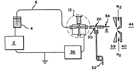
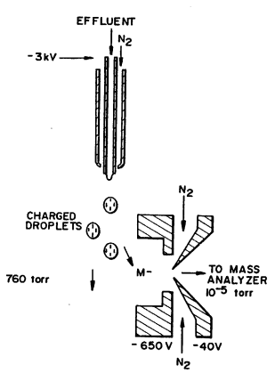
In the l-h-s figure, 12, represents the liquid junction coupling. In the cross, there was a small gap (10-20 µm) between the CE separation capillary and the sprayer needle which was claimed to be of SST. The purpose of the liquid junction coupling was twofold. On the one hand, providing an electrical contact (36) by which the electrospray voltage was applied. But secondly, with the recognition that the EOF might be as low as 0.1 µL/min, the solvent reservoir served to deliver some extra solvent by gravity flow to become compatible with the ion spray. On the r-h-s figure, the pneumatic assistance of spray formation by nitrogen gas is indicated.
Nevertheless, this approach did not make it into a viable commercial product. The requirements to the liquid junction coupling regarding positioning of the capillary and spray needle and overall reliability proved unsatisfactory. Also notice that in both approaches, the electrospray voltage is applied to the SST spraying needle.
![]()